Tube furnace method for the determin ation of toxic product yields in fire effluents
BS 7990:2003 pdf free.Tube furnace method for the determin ation of toxic product yields in fire effluents.
yield mass of an effluent component divided by the mass loss of the test specimen associated with the production of that mass of the effluent component.
volume yield volume of an effluent component at standard temperature and pressure (20°C and 101.325 kPa) divided by the mass loss of the test specimen associated with the production of that volume of the effluent
component
4 Principle
A test specimen, in granular or rod form, is placed in a clear heat resistant quartz boat, and introduced at a constant rate along a clear quartz furnace tube through the hot zone of a fixed tubular furnace. A stream of primary air is passed through the quartz furnace tube and over the test specimen to support combustion. The fire effluent is expelled from the quartz furnace tube into a mixing and measuring chamber, where it is diluted with secondary air to a nominal total air flow rate of(50 ± 1) Fmin’ through the chamber and then exhausted to waste. Samples of the effluent mixture are taken from the chamber for analysis.
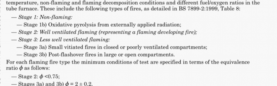
The decomposition conditions in the furnace are set using different combinations of temperature and primary air flow rate in separate test runs, to model the decomposition condition in a range of fire stages as characterized in BS 7899-2.
For flaming decomposition conditions. different fuel/oxygen ratios and hence different equivalence ratios. arc obtained when different primary air flow rates are used in relation w the constant rate of introduction of the fuel.
The aim in each test run is (after an initial settling down period when decomposition conditions and product yields may be variable) to obtain stable, steady state, conditions for at least 5 mm during which the concentrations of effluent gases can be measured. The longer the duration of the test run the longer the period during which steady state conditions can exist. The duration of the test run depends upon the length of the specimen (which is limited by the length of the test specimen boat and the quartz furnace tube) and the rate of test specimen advance. The time taken for steady state conditions to be established varies depending upon the nature of the test specimen and the test conditions. The test specimen boat and quartz furnace tube lengths specified are the minimum lengths usable for obtaining 5 mm of steady state conditions for all materials under all decomposition conditions.
NOTE The arrangement of the apparatus is shown in Figure 1.
5.1 Tube furnace, with a heating zone of length 500 mm to 600 mm and an inside diameter of 40 mm
to 70 mm. equipped with an adjustable electric heating system capable of controlling the final temperature to within ±2 % of the nominal temperature. The heating element should preferably be rated at 1 300 °C.
NOTE A furnace as descnbed in IEC 60754-2 is suitable.
5.2 Quartz furnace tube, as shown in Figure 2. made of clear heat resistant quartz, resistant to the effects of fire effluent and with a wall thickness of(2 ± 0.5) mm. approximately concentric to the furnace bore. The outside diameter shall be such as to permit a smooth fit within the tube furnace (5.1) and to allow
expansion at operating temperatures (see Note 1).
The inlet end of the quartz furnace tube shall have a closure with openings in it to allow the primary air inlet and the test specimen boat drive bar to pass through. The outlet end of the quartz furnace tube shall pass through a heat resisting sealed gland (see Note 2) and shall protrude approximately 55 mm into the mixing and measurement chamber (5.6). The tube length shall be sufficient to allow this and also to allow the test specimen boat to rest in it. outside of the tube furnace (see Now 3). The quartz furnace tube shall be cleaned after each test (see 5.3. Note 3).
In addition, a quartz tube of outside diameter approximately 5 mm and inside diameter approximately
3 mm may be introduced 100 mm into the quartz furnace tube along the top edge to sample the atmosphere inside the furnace tube for the measurement of oxygen concentration.
NOTE I A quartz furnace tube with an outsidt diameter of 47.5 mm i 1 mm has been found to be suitable for use with tube furnaces of 50 mm to 65 mm internal dianieter.
NOTE 2 A gland made from glass wool inside a brass collar has been found to be suitable
NOTE 3 For use with a 600 mm tube furnace and test specimen bouts of up to 800 mm a quartz furnace tube length of 1 600 mm has been found to be suitable.
5.3 Test specimen boat, as shown in Figure 2, made from clear heat resistant quartz, having the following minimum dimensions:
— diameter of cross-section (41 ± 1) mm (see Note 1);
— length 800 mm (see Note 2);
— wall thickness 2 mm ± 05 mm.
The test specimen boat shall be cleaned after each test (see Note 3).
NOTE 1 A convenient method for making a suitable test specimen boat for a 47.5 mm diameter quartz lurnuce tube is louse
an 800 mm length of quartz tubing with a nominal diameter less than that of the furnace’ tube (a nominal diameter of 41 mm is
suitable). This can then be sliced in half lengihwavs to provide a Lest specimen boat with a semi.eireular cross.section, with nominal dimensions 41 mm diameter ofcross.section, 18 mm depth and 800 mm length, Scmi.circular quartz end pieces then need to be fused in place. A test specimen boat diameter of just less than the quartz furnace tube internal diameter should be used to provide the
maximum specimen capacity.
NOTE 2 A test specimen boat length of less than 8(X) mm has been found to be insufficient for obtaining 5 mm of steady state
conditions for many materials under some decomposition conditions. A test specimen boat length of 800 mm has been found suitable for most situations.
NOTE 3 A convenient method of cleaning both the test specimen boat and the quartz furnace tube is to remove obvious residues mechanically, then fire at 1 000 °C. followed by washing in water to remove any inorganic residues.
5.4 Test specimen boat drive mechanism, connected to the test specimen boat by a hooked drive bar passing through a gland seal (see Note 1) at the input end of the quartz furnace tube to enable the test specimen boat to be advanced through the quartz furnace tube (see Note 2).BS 7990 pdf free download.Tube furnace method for the determin ation of toxic product yields in fire effluents